Monday, 12 August 2019
Wednesday, 11 October 2017
Tuesday, 9 May 2017
#16x2 LCD DISPLAY interfacing with ATMEGA 16
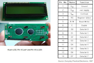
16x2 LCD DISPLAY

Now you can see in the above figure showing the 16 PIN, 16 characters, 2 line display.
LCD interfacing with atmega16: In both left and write most pis are Negative and both second last pins are Positive, But the PIN number 1 , 2 & 3 are mandatory to give supply otherwise you can not see the display.
you may leave pin number 15 & 16 pin without connection because it is connected with LED inside this. As you know we doesn't connect LED without any resistance so it has resistance inside this. If we leave this pins it will not glow light. But it can show the display.
RS = 1;
R/W = 0;
EN = 1;
delay(5 mili second)
EN = 0;
this will decide what we are sending above it , is data.
you may leave pin number 15 & 16 pin without connection because it is connected with LED inside this. As you know we doesn't connect LED without any resistance so it has resistance inside this. If we leave this pins it will not glow light. But it can show the display.

In this figure you can see the DATA pins and control pins,
In case you want to give command for display the cursor you will have to give
RS = 0;
R/W = 0;
EN = 1;
delay(5 mili second)
EN = 0;
As you can see we are enabling EN and pulling it down back , it is to latch the data (command) in the LCD, in case we does not pull it down it will miss match the data and command, it will unable to decide which one is command and witch is data, will give some garbage display.
In case you want to display data or string you have to give
R/W = 0;
EN = 1;
delay(5 mili second)
EN = 0;
this will decide what we are sending above it , is data.
**********************************************************
HERE I AM GOING TO SHOW YOU A HEADER FILE OF LCD 4-BIT MODE
BASED ON ATMEGA 16 :---
void lcd_init();
void lcd_cmd(unsigned char cmd);
void lcd_data(unsigned char data);
void lcd_str(char *str);
void lcd_init()
{
DDRB = 0xff;
lcd_cmd(0x02);
lcd_cmd(0x28);
lcd_cmd(0x0f);
}
void lcd_cmd(unsigned char cmd)
{
PORTB = cmd&(0xf0);
PORTB |= (1<<2);
PORTB &=~((1<<0)|(1<<1));
_delay_ms(5);
PORTB &=~(1<<2);
PORTB = (cmd<<4)&(0xf0);
PORTB |= (1<<2);
PORTB &=~((1<<0)|(1<<1));
_delay_ms(5);
PORTB &=~(1<<2);
}
void lcd_data(unsigned char data)
{
PORTB = data&(0xf0);
PORTB |= ((1<<0)|(1<<2));
PORTB &=~(1<<1);
_delay_ms(5);
PORTB &=~(1<<2);
PORTB = (data<<4)&(0xf0);
PORTB |= ((1<<0)|(1<<2));
PORTB &=~(1<<1);
_delay_ms(5);
PORTB &=~(1<<2);
}
void lcd_str(char *str)
{
while(*str!='\0')
{
lcd_data(*str);
str++;
}
}
Thursday, 20 April 2017
BLUETOOTH CONTROLLED HOME AUTOMATION
THIS IS THE VOICE CONTROLLED HOME AUTOMATION

In this project Arduino uno is used. you can also make it using different controller like AVR, 8051, ARM, PIC etc.
To operate the appliances three relays are used through relay deriver (ULN-2003) , this is the 16-PIN IC, in other hand u can also use different IC of relay like ULN-2803 this IC is of 18 pin.

::"for more about the Embedded projects you can also go through my you tube channel"::
As you can see in the figure green connectors are for main supply also connected to appliances.
To operate these appliances serial communication is used of 9600 BAUD RATE.
And one android application (AMR_Voice) to connect Bluetooth module which is HC-05.
Different different application sends data in different different strings , so if you are trying to use any another application so you should see first in what string it is actually sensing. To see that you may use hercules serial terminal, that will allow you to see the string you are getting in micro controller.
By comparing these strings you can operate you appliances.
In this circuit the green led is to show the power supply in circuit, and white LED's , each white LED is simultaneously connected to each relay to show that which one relay is ON.

In this project used components are:
- Arduino_uno
- 12v relay
- ULN2003
- 16 pin IC base
- male strips
- female strips
- DC jack
- 7805 (regulator ic )
- capacitor (25v 1000uf)
- resistors (470E)
- led (5mm)
- Female connecting wires
- Usb to b-type cable (to load program)
- one Android phone
- HC-05 (Bluetooth module)
- one adopter.
- Supply connector

::"for more about the Embedded projects you can also go through my you tube channel"::


Subscribe to:
Comments (Atom)